Author: Guenther Shepherd

  • Teaching Sailing with a Boat That Sails Itself.

    Teaching Sailing with a Boat That Sails Itself.

    A few years ago, I was training to become a sailing instructor. After I completed my formal instructor training, I spent some time as an assistant teacher, helping out my friend and sailing mentor Mike Jarvis. In-between lectures we talked about the curriculum, and he would share his personal thoughts on the topics. During one of these discussions, he said something I hadn’t heard before; He pointed out that the cumulation of beginner’s class was understanding how to orient the sails, wind, and boat to each other. Once a sailor understands how to orient the sails, boat, and the wind, they’re sailing. It all boils down to this 3-way relationship.

    This reminded me of another 3-way mechanism, the planetary gearbox. It seemed possible that a planetary gearbox could mechanically match the way the sail, wind, and boat rotate around each other. If that gearbox were installed in a model boat, then that boat could show students how to sail. This possibility fascinated me.

    I didn’t know it at the time, but I had just taken the first step in a year’s long project. A project that would span numerous prototypes, heaps of feedback, and would culminate in the creation of a one-of-a-kind teaching aid. In this blog post I’ll retell the story of how I taught sailing with a boat that sails itself.

    The Plan

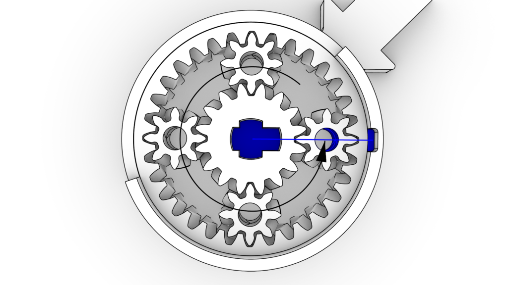
    The first order of business was designing the planetary gearbox. Planetaries are wonderfully compact but only certain ratios between the inputs are possible. This became a problem immediately. I was getting invalid results when I tried to generate a gearbox for the ratios I needed. The project stalled at this point and only after a healthy amount of research, experimentation, and one late night realization, did I find my gearbox. Check it out in motion in the video below:

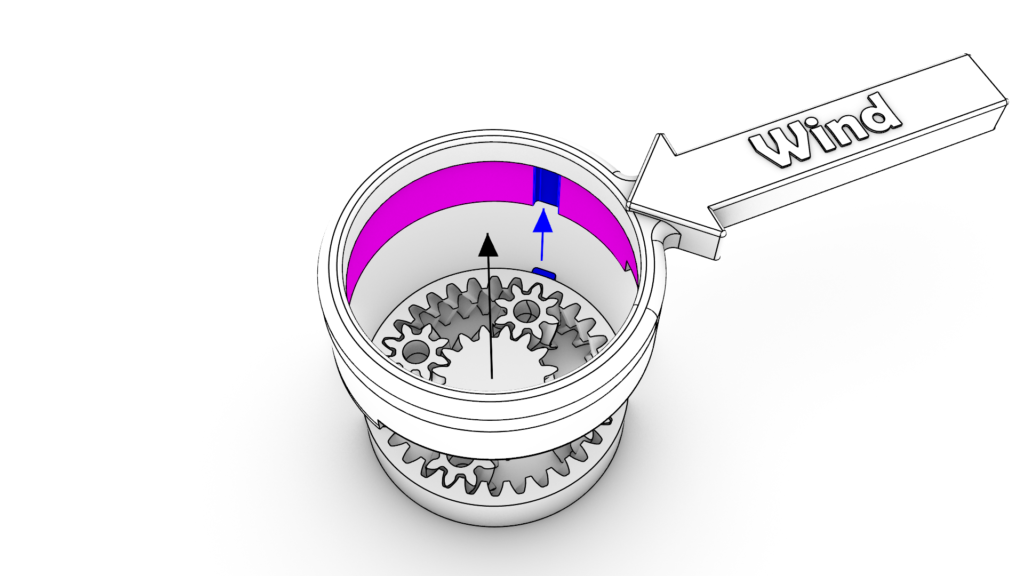
    The solution was possible with this arrangement of inputs:

    • The green ring gear rotates the wind.
    • The red carrier rotates the sail.
    • The cyan sun gear rotates the boat.

    This approach oversimplifies sail trim a little, but is close enough for teaching beginner sailors. Another limitation of my approach is that the wind has to be locked to one side of the model. This feature was also omitted for simplicity but, as I will discuss later, it should have been included.

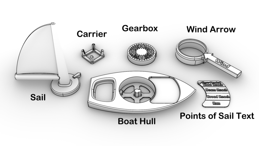
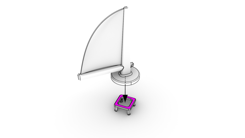
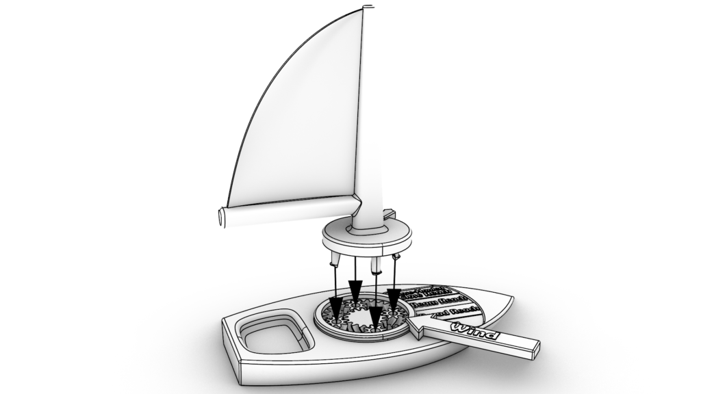
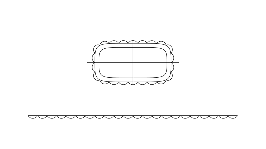
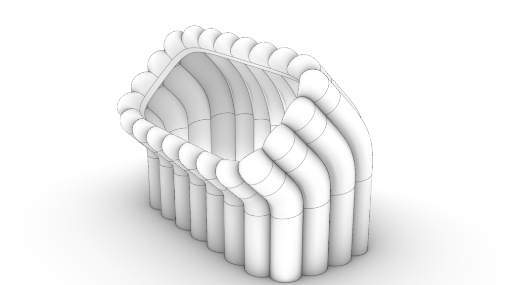
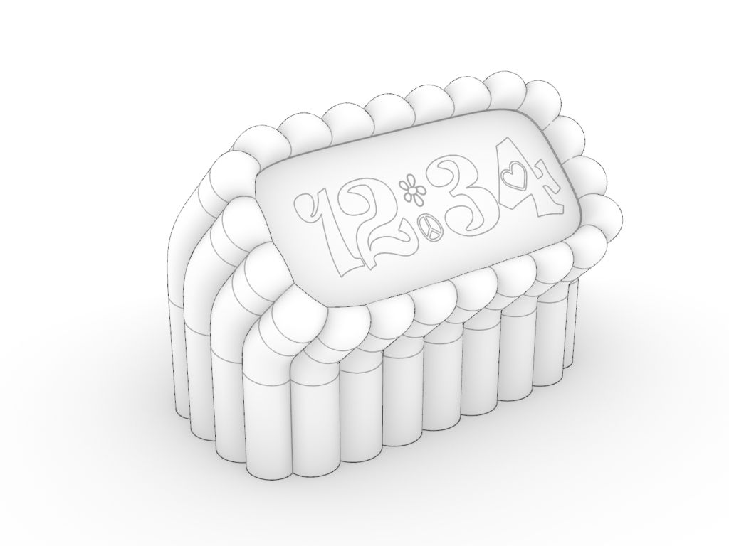
    With the planetary gearbox designed, it was time to make the rest of the model boat. I fairly quickly sketched out how the sails, wind, and boat could go together.

    Initial sketches of the sailboat mechanism.

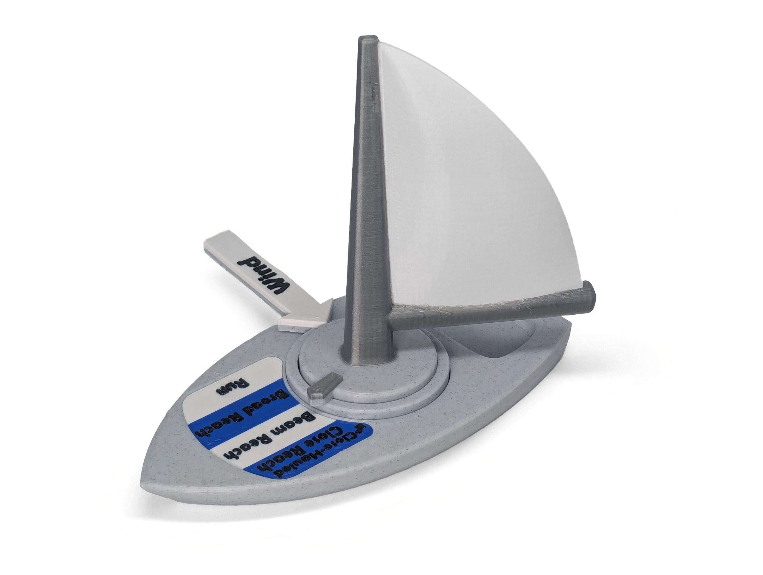
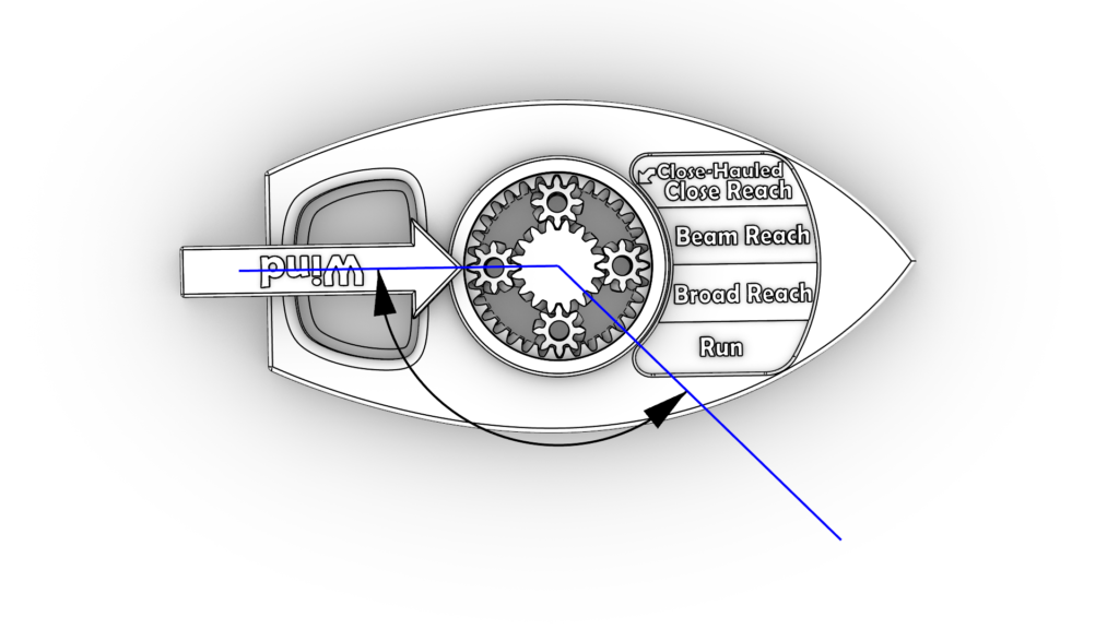
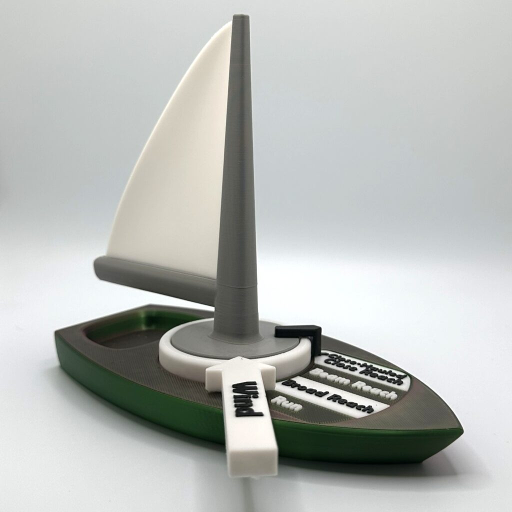
    While sketching I thought up another feature: a dial that indicates the current “Point of Sail.” For the unfamiliar, the “Points of Sail” describe how a boat and its sail are oriented in the wind. The 5 points of sail are: Close Hauled, Close Reach, Beam Reach, Broad Reach, and Run1. Since the planetary gearbox is already a mechanical calculator for the Point of Sail, the dial indicator was an easy addition. I was hopeful that having the nomenclature on the model would help novice sailors attach words to what they see. With a clear vision, I was ready to start modeling the parts.

    Drafting

    My intent was to design a model that anyone could 3D print. Basically, a 3D printable kit. Having printed other people’s files, as well as publishing my own, I knew there were a few guidelines to follow when drafting models to share. Just to name a few:

    • Avoid requiring external hardware.
    • Minimize the use of supports.
    • Avoid tight tolerances.
    • Provide an assembly manual.

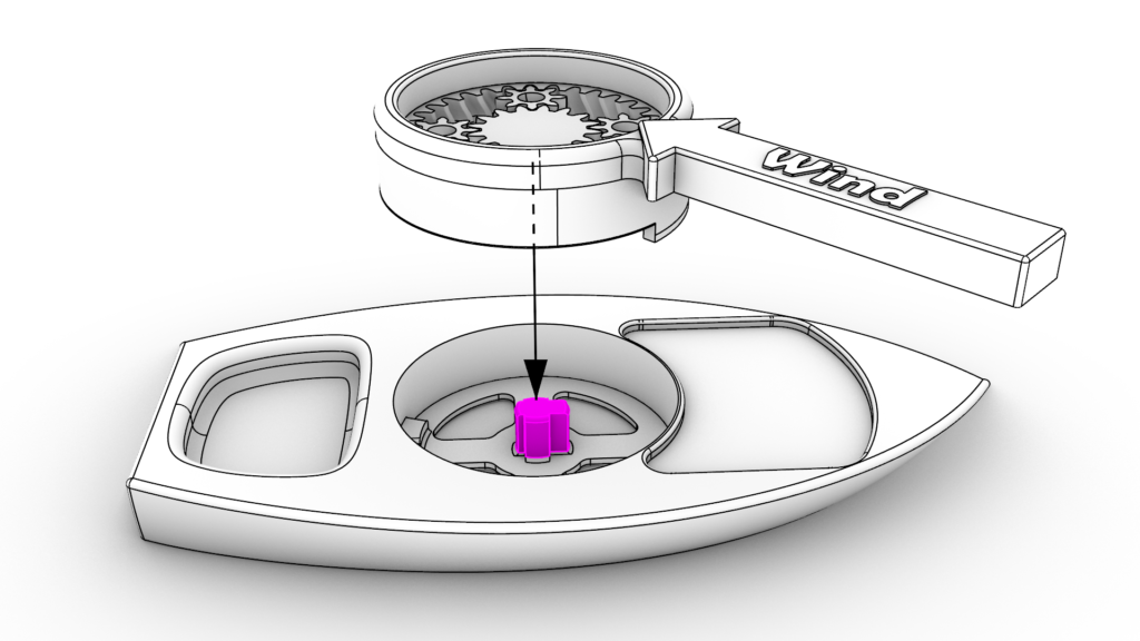
    To explain how I worked around these constraints I’ll walk through the process of designing the gearbox. Planetary gearboxes are hard to assemble, so I made the gearbox “print-in-place.” This means that the gearbox comes out of the printer fully assembled. This convenience comes at a cost though, because now the printer needs to be very precise or else the gears will melt together during printing. Since this needs to print on other people’s printers too, I can’t assume that the printer will be precise. To accommodate this, I had to increase the spaced between the gears. Perversely, when there’s more space between gears, a precise printer will produce a wobbly gearbox. So, in order to mechanically stabilize the wobbly gearbox, I had to recess it into the boat hull. The resulting gearbox is easy for anyone to manufacture, but at the cost of design time.

    Print-in-place planetary gearbox.

    With my first sailing class coming up I had limited time to work around these constraints. Like any work done on a deadline, I had to make compromises. Some of these compromises I got right, and others I would have to revisit. In a later section I’ll discuss the feedback I got from the wider 3D-printing community and how I integrated it.

    your 360 images

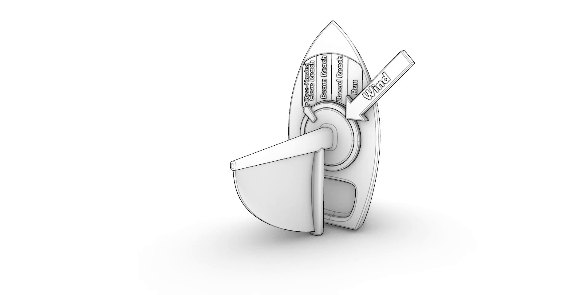
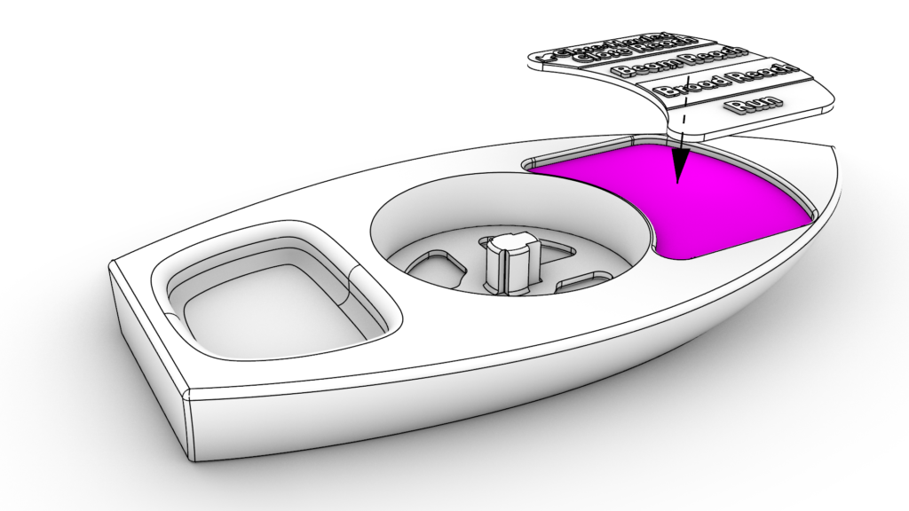
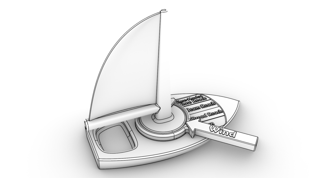
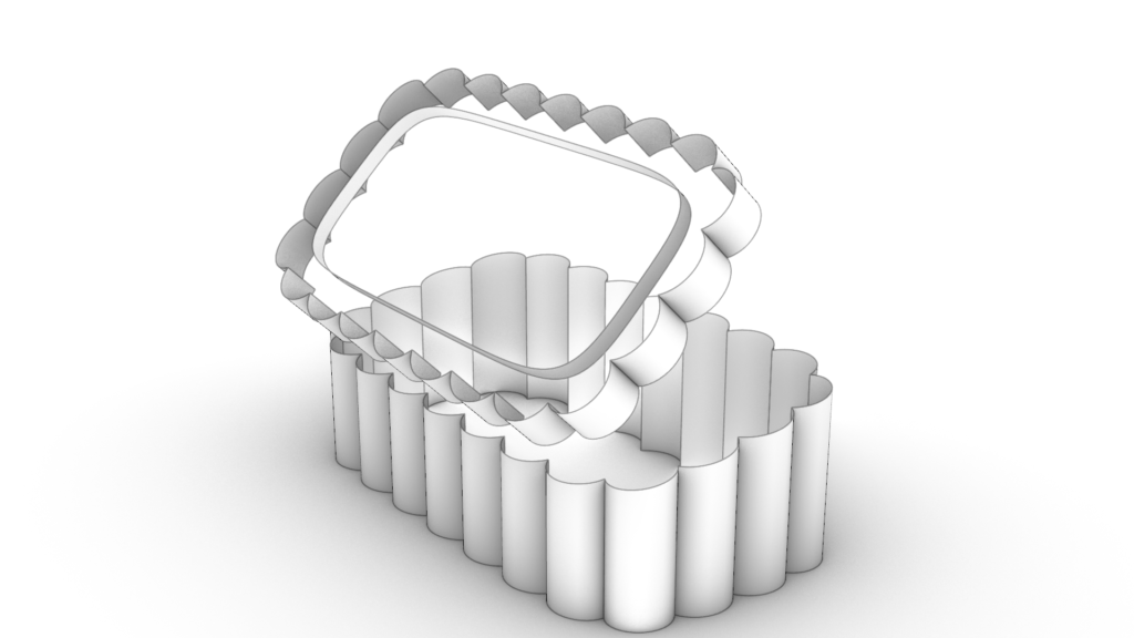
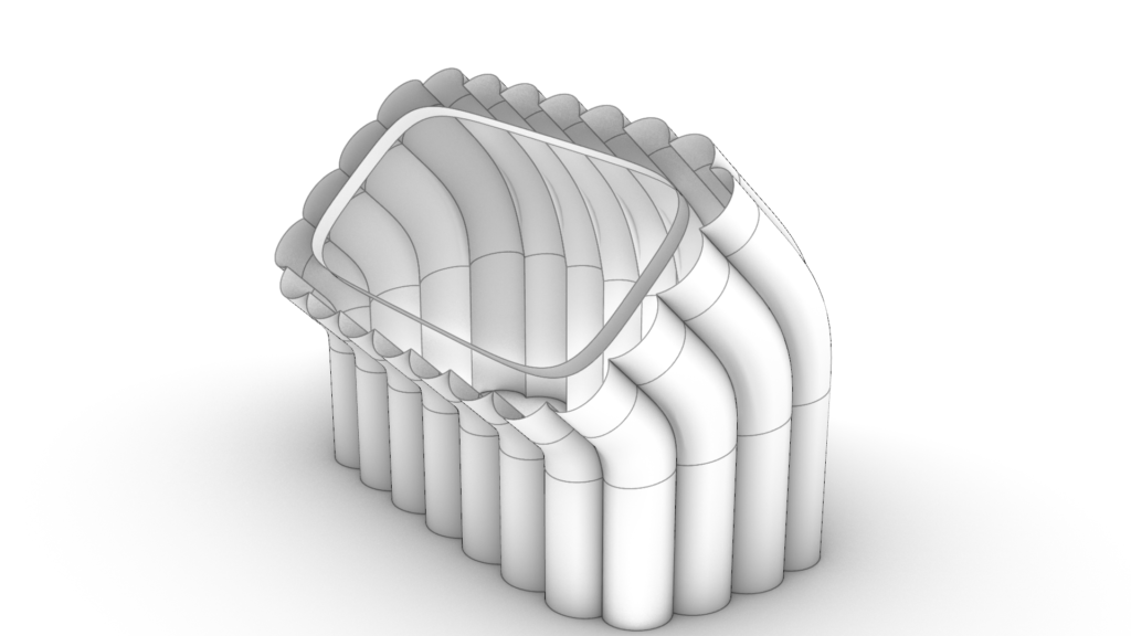
    Interactive sailboat assembly. Click and drag to explode the CAD model.

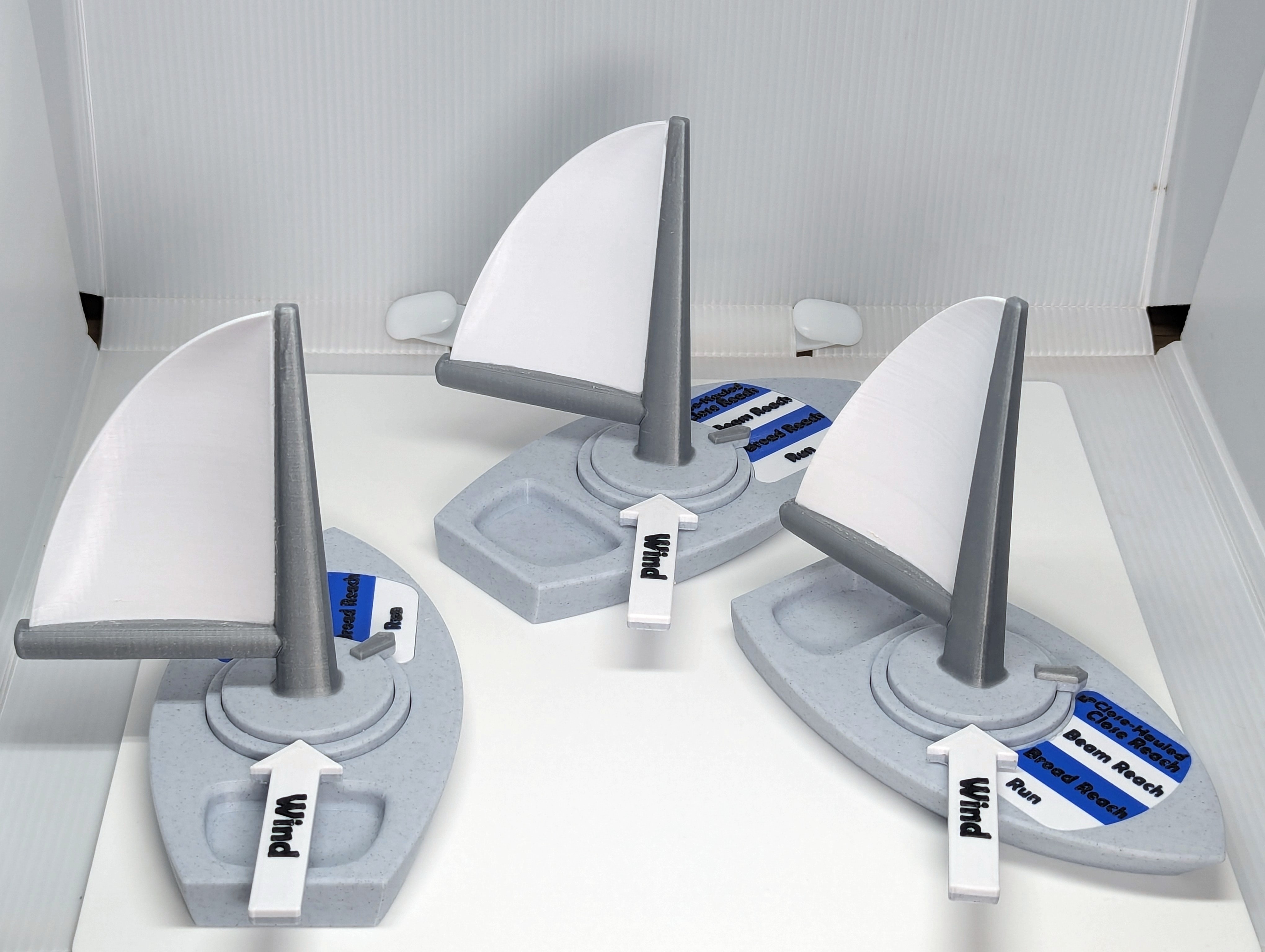
    With the drafting nearly complete I started the process of tuning the overall fit-and-finish with test prints. After a few iterations the functionality was working great! Check it out in motion:

    Top-down view of a 3D printed model in motion.
    Bottom-up view of the 3D printed model in motion.

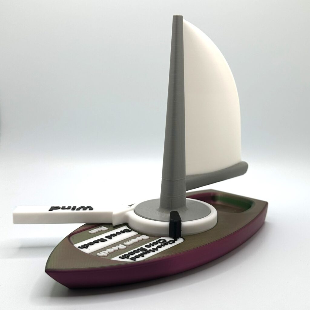
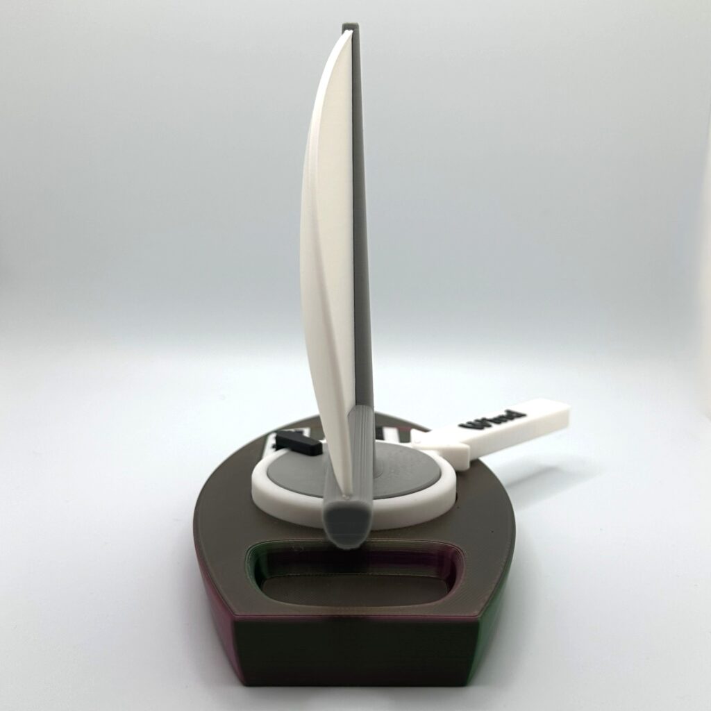
    The model and a sailboat going through the points of sail together.

    The version shown here is the final version. In the next part I’ll describe how the first working prototype was improved on by integrating feedback from my students.

    Field Tests

    Two sailors playing with the self-trimming sailboat.

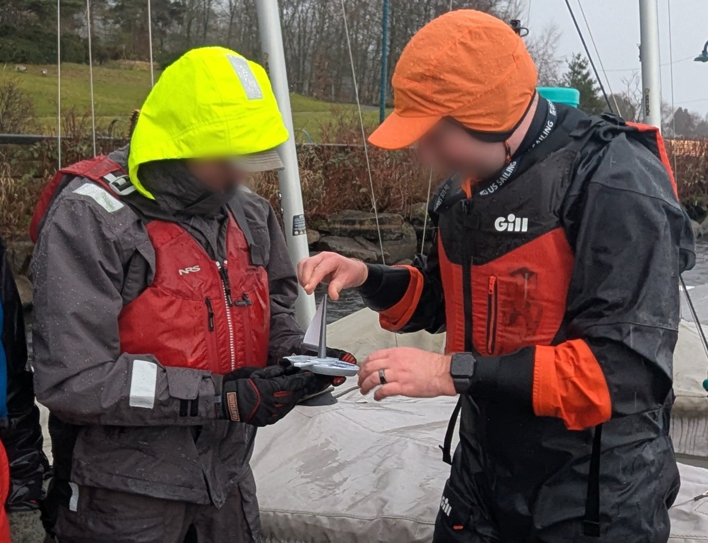
    I had barely finished printing the first batch of sailboats in time for my class, having to stay up late assembling the boats. As part of my sail trim lecture, had my students partner up and play around with the models.

    Responses varied person to person. After the activity, a few students were eager to talk about their new sailing insights. For others, this was just a small part of the overall curriculum. I watched my students sail after the activity, and my own observations matched what students were telling me; For a small number of people, it made a big difference. While the first version saw some success, I was also taking note of the issues students were having.

    (Left) The first working prototype that was used in class. (Right) The final design after integrating feedback. Note, the purple and gold color scheme was picked by the sailing club this print was gifted to.

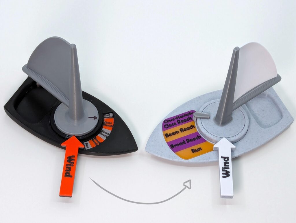
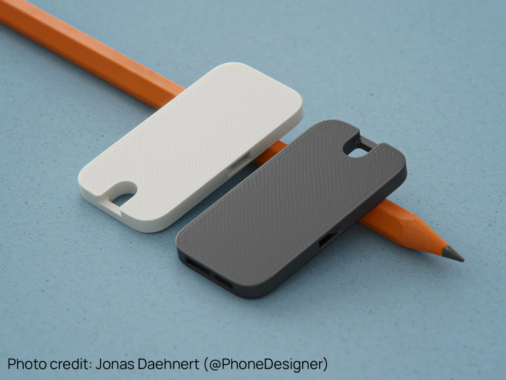
    The biggest issue with the model was the size of the text. I knew the text layup wasn’t great, but I was surprised by how bad it was in practice. When the boats were passed around, students were immediately squinting, and a few had to run off to find their reading glasses. One retirement-aged student entirely gave up on trying to read it and had his partner read everything out loud for him. In the next iteration, I widened the entire model so the text could be nice and big.

    The model also became useful for teaching in ways I hadn’t plan for. While articulating the model, students were asking me if their boat had gone through a tack2. The model wasn’t particularly helpful in explaining tacks, because the internal mechanism physically won’t let it tack. If I could modify the model to be able to tack, then the full concept could be explained with just one prop. Unfortunately, adding tacking would require a total mechanical overhaul, something I wasn’t willing to do.

    A fleet of the model sailboat at various points of sail.

    I also brought the model to a few sailing club events. While experienced sailors were interested in it, they only saw it as a novelty. My fellow sailing instructors, on the other hand, were very engaged. They were quick to suggest new functionalities too, especially tacking. Mike, who originally inspired the project, was especially keen on getting some to use for his classes. After enough interest from the other instructors, I left the models I had printed for my class in the classroom for the other instructors to use.

    At the end of summer, I checked in with the other instructors to get some feedback on how the models did in class. The main issue was durability. By the end of the summer, only a single model remained intact and in one piece. While I knew the design was a little delicate, real-world users were much harder on the hardware than I expected. Before printing the next batch, I made some structural improvements to the design and also switched to a tougher plastic.

    With a year’s worth of feedback integrated, I felt the model was ready for the wider world. In the next section I’ll discuss the publication of the model and its reception online.

    Publication

    There was one last problem to solve before I could publish, how to find my audience. While I knew my audience was sailing instructors, the problem was that they’re a small group, and an even smaller portion of them have a 3D printer. While I could have pivoted to selling a complete product, I felt the idea would still have a further reach if I kept it free. My solution was simply to make printing the model as low friction as possible. I spent much more time than usual documenting and explaining the project, even making a comprehensive assembly manual.

    With everything ready, I finally published the files on printables. The model soon found a small but enthusiastic following. As expected, the strongest engagement was coming from sailing instructors. However, there were also a fair number of 3D printing hobbyists who were printing the model for the sailor in their life. This was something I hadn’t anticipated, and I was happy to see that my efforts to streamline the printing were encouraging others to share the design.

    As more people took an interest in the model, I felt energized to iterate on the design. A few users were reporting issues printing some of the parts, so I re-drafted those problem parts until they were easier to print. I also removed the “non-commercial” clause in the license. A user had expressed concern about using the model in the “commercial” context of a sailing class, so I felt the license was becoming an unnecessary barrier. There were also some international users that were looking for help localizing the mode, so I released a blank version for them to add their own language too. Over time, these small adjustments made the model more accessible to all.

    Reflection

    I have an engineering background, and that defined my initial approach. In engineering, a solution is prescribed by the engineer and then judged against cost and performance. However, as this project went on, I drifted towards something more conversational. By the end, I saw my solutions more like suggestions. Suggestions that I could improve on by integrating the stories and experiences of others.

    For a concrete example, look at how I started the project by diving into the technical details of the gearbox. During this technical phase, I decided to removed tacking as a feature. By the time I was collecting feedback on the prototypes, adding tacking back would have required re-doing the entire model. Instead of diving into the technical details, I should have had a conversation. I should have spent more time pitching the concept to my peers and then built up a list of what features mattered.

    By the end of the project, integrating feedback from others felt as natural as implementing my own. And the model is better for it. Without the stories and experiences of other, I could never have made the model as accessible as it is now.

    Foot notes

    1. Confusingly, there is some disagreement as to how many Points of Sail there are. Some materials skip Close Hauled, while others add an additional one, the Dead Run. I simply included the 5 that were taught in my first sailing class. ↩︎
    2. For the unfamiliar, a “tack” is a sailing maneuver. To tack a sailboat, you turn it towards the wind and then keep turning until the sails are filled with wind from the opposite side. ↩︎
    3. Image credit @SarahKnudsen_2651684. Used with permission. ↩︎

  • “What’s the WIFI” + Alarm Clock

    “What’s the WIFI” + Alarm Clock

    My neighbor runs a little vacation rental and is always forgetting the password for the guest WIFI. It seems that sticky notes are just too easy to lose, so I set out to make something a little more permanent to keep the login info on. Since I was going to the trouble of making something, I tried to add a little touch of fun to the design. As you will see, the final design ended up taking on a life of its own, spurring a second project and then dreams of something bigger.

    The Plan

    I broke the design into two parts, one for function, and the other for fun. The principal function would be served by a 3D printed plaque inscribed with the login info as well as QR code that can be scanned to automatically logon. The fun part would be an eye-catching stand for the plaque that would draw in the user and bring a pop of style to the room.

    The design of the stand was based around my neighbor’s personal tastes. I drew inspiration from his love of the American 60s: a time of color TV, groovy fashion, and hippies. To channel this I brough in bright colors, a corduroy texture, and a splash of psychedelic style.

    Drafting

    The CAD for this model was simple, so I’ll dive into the methodology more than usual. The process started with drawing the cross-section of the plaque and the stand as spline curves.

    The next step was drafting the side profile. Having already roughed out two side profiles in the ideation phase, I picked the second option.

    With the curves complete, I could start to build the surfaces. I made all the straight sections by extruding the existing curves. The bent surfaces were made by blending between extruded surfaces.

    From there I just needed to lay up the text and QR code for the plaque, and voila!

    Nice.

    From the beginning of the drafting process, I was planning to experiment with the surface blend tool. A more conventional approach might have been to use a tool that’s guaranteed to preserve the cross-section, like a “sweep.” I felt a sweep was too stiff in this case, as it wasn’t producing the side profiles I wanted for the bent surfaces. In this case, the surface bend did well enough at preserving the cross-section around the bend with minimal manual adjustments from me. I think this model is a nice example of how a design can grow naturally from thoughtfully planned NURBS geometry. From this, I’d expect the style of this model to be easily repeatable. Corduroy for all!

    Reception

    My neighbor was totally psyched. He loved the shape, colors, functionality, the whole deal. Here’s how it looks in the rental:

    He noted that guests seemed to like it too. He mentioned this matched the changing trend in his guest’s preferences. He explained that guests now want to be autonomous during their stay and he lamented the loss of personalized hospitality. Soon he was coming up with all kinds of ideas of uses for these little plaques around the rental, such as having a QR code to an online self-check-in. An interesting project I might come back to another time.

    Alarm Cock

    Riding high off my neighbor’s enthusiasm, I found myself wondering what else I could do with this design. I tossed a few ideas around for it and decided it could make one groovy alarm clock.

    I drew a few stylized clock faces to see what worked.

    I liked the option 3 the best, so I did a full render for it. Here’s how it came out. Go ahead and give it a spin!

    your 360 images

    I also experimented a bit with using AI to render the alarm clock in a bedroom. I supplied my render of the alarm clock then described the rest of the scene. The results incorporate the clock surprisingly well.

    It might be fun someday to try and get a full prototype of this up and running.

    Corduroy Joy

    This project was a joy to work on. Starting with a tiny scope, and a concise need was a comfortable place to start, and by the end I found myself wishing I could keep working on it. The positive feedback from my neighbor was a green light for more development. And his suggestions for other uses in the rental could justify making a whole bunch of objects in this style. My alarm clock idea supports another functionality for this fun design. Considering how simple the CAD workflow was for this project, more is sure to come.

    That’s all for now!

  • Tessellating Art and the Einstein Problem

    Tessellating Art and the Einstein Problem

    While researching the recently solved “Einstein Problem,” I stumbled upon talented individuals who were using this new discovery to build mathematical art. These people equipped me with the tools and inspiration to create some works of my own. In creating this art, I found a new connection to M.C. Escher, a master of tessellation art.

    The Einstein Problem

    The einstein problem asks if there exists a shape that tiles (covers without gaps or overlaps) a plane aperiodically (without a repeating motif). Just recently a small research team discovered that tile, solving the einstein problem. They discovered not just one tile but an entire family of tiles. They named this family of tiles ‘Specters’.

    (Left) A Specter with stylized polyline edges. (center) The underlying edge arraignment of all Specters. (Right) A specter with stylized curved edges.

    I was disappointed to learn that the einstein problem has no relation to Albert Einstein. In this case we’re referring to the literal German translation, meaning “one stone”.

    A tessellation of Specters. The animation fades between differently stylized edges.

    Getting Hands On

    The initial discovery was made by David Smith, a retired print technician and self-identified “shape enthusiast.” In his pragmatic methodology he used both software and cardboard cutouts to experiment with tessellation. In turn, I wanted to do some hands-on experimentation too.

    I went online to find a tile file for 3D printing, and found more than I expected. People have been decorating the tiles so that when they’re tessellated a design takes form. I downloaded a few of these designs, 3D printed them and then made these mosaics.

    Various mosaics made with 3D printed tiles.1

    Notice the gaps in the center of each star in the last image? This is a great example of something unique to aperiodic monotiles; Its only possible to create a repeating motif by leaving gaps between tiles. The only way to close the gaps is to let the tiles flow into aperiodic tessellation. Laying the tiles down this way has an unusual feeling to it, there’s no regular pattern to guide tile placement, and yet, each additional tile has a place it fits perfectly. Every tile has the same simple decoration, but when they’re together a complex design emerges.

    Tools

    Inspired to create tile decorations of my own, I set out to find the necessary software tools. After some searching, I found exactly what I was looking for on the forum for Rhino 3D. This thread contains an excellent assortment of both scripts and art. I modified an existing tessellation script to work on my tile decorations. I used Rhino 3D to draw my decorations on a source tile and then used Grasshopper to tessellate them.

    (First) A single decorated tile that’s used to tessellate the plane. (Second) A glimpse of the grasshopper script used.

    After generating the tessellation, I transferred the curves into Adobe Illustrator for coloring.

    Art

    When tiles come together, something new emerges. This artwork is inspired by structures with emergent characteristics e.g. a network of roads, a multicellular organism, an organic molecule. Everyone sees something different.

    Drag the bar on each image to reveal or hide the individual tiles.

    Untitled 1

    Untitled 2

    Untitled 3

    Untitled 4

    Untitled 5

    Untitled 6

    Repetition Emerges

    Despite being aperiodic, repeating shapes start to emerge as we zoom out.

    Untitled 4, Large

    Notice the triangle-like pattern? This isn’t a trick of the eye; the repetition is real.

    When Specters are tessellated, they happen to organize into small groups. These small groups tile in the same as hexagons or triangles.

    Animated fade between tessellated Specters2 and tessellated hexagons.

    According to the original paper on Specter, there is always an equivalent tessellation of hexagons, but the two can’t perfectly line up. This is both the reason for orderly patterns that emerge, and why their imperfect.

    I had designed the tile decorations so that larger structures would be formed when tiles were brought together. However, what I had not anticipated is that those structures would begin to look orderly as the tessellation expanded. It reminds me of the emergent symmetries in our own world, like how a how a city made of so many roads and buildings will expand into an imperfect circle.

    Returning To Escher

    A public sculpture inspired by tessellation art of M.C. Escher.3

    While my art was made to be aperiodic, the specter of periodicity crept in. It turns out that art made by tessellating Specters was not so different from art made by tessellating hexagons.

    I’m reminded of the master of tessellating art, M.C. Escher. His work was my first introduction to mathematical art, and he has long been inspiration to me. I spent the final hours of this project examining his work with new eyes. I encourage the unfamiliar to peruse his playful tessellations as well.

    Citations

    1. 3D modeling authorship for these 3D printed tiles are @bengineering on Thingaverse, @ateldsign on Printables, @ateldsign on Printables, @CarlosLuna on Printables. ↩︎
    2. This diagram comes from the paper “A chiral aperiodic monotile” by David Smith, Joseph Samuel Myers, Craig S. Kaplan, and Chaim Goodman-Straussis. It’s released under the CC BY license (International 4.0). My modifications to the diagram are shared alike. ↩︎
    3. Photograph by Bouwe Brouwer. It’s released under the Creative Commons Attribution-Share Alike 3.0 Unported license. ↩︎
  • 3D Printing Merch For Sailors

    3D Printing Merch For Sailors

    This last spring I set out to develop a piece of merchandise for the Renton Sailing Center (RSC). To make things fun, I self-imposed a constraint to use my 3D printer. The final product found its way into classes, races, and outreach, connecting with sailors new and old.

    The product is just a branded whistle on a lanyard. While simple in appearance, this product took a few wrong turns in development before ending up where it needed to be.

    The final product.

    What To Make

    I settled on whistles since they’re both useful to sailors and cheap to make. As an added bonus, there’s already countless open-source whistle designs to build off of. After a bit of research, I found a model that would be perfect for adding my own graphics onto: The Flat Pocket Whistle by Jonas Daehnert.

    The First Prototype And Feedback

    I made a little vector graphics sailboat and embossed it alongside the RSC initials.

    First attempt in various sizes.

    Then I collected feedback from members about the design. There were two major complaints:

    • Members felt no connection to graphics and colors used.
    • Sailors struggled to find storage for a loose whistle on their sailing outfit.

    The New Design

    Back to the drawing board! First to get fixed was the graphics and colors. I was sad to see my little sailboat drawing go, but a much better graphic was clear to me now. I vectorized the Renton Sailing Center’s Burgee and updated the colors to match.

    Final graphics.

    Using an established symbol increased people’s connection with the whistle.

    I addressed the issue of storage by adding a cheap lanyard to each whistle. While I was disappointed that my product was no longer 100% 3D printed, but this change was necessary. I was surprised by how readily people accepted the whistle on a lanyard compared to the confusion that came before.

    Whistle on lanyard.

    To dispense the whistles, I invited the RSC’s Activities Coordinators to give away the whistles at their discretion. Whistles could be given out to anyone who participates in club activates like volunteering or taking a class.

    Conclusion

    Over this last summer about 100 of these whistles went out to the community. They went to kids at outreach events, students who completed classes, members who volunteered their time, and a myriad of others.

    This simple design is both useful and put smiles on faces.

    Me rocking the RSC whistle.

  • Hello world!

    Hello world!

    Welcome to my personal website. I’m putting this together as a way to share my thoughts with the world. I’ll be making digestible write ups about my projects, processes, and products. Navigate to any of my blog posts and get reading!